MMA2260 Accelerometer Demo
This little board demonstrates the capabilities of the MMA2260 +/- 1.5g X-Axis Micromachined Accelerometer. As you tip it back and forth, LEDs light up to show the magnitude and direction of the G force.
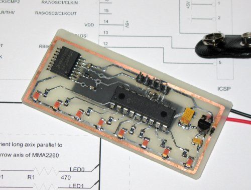 The MMA2260 is the fat SOIC 16 in the upper left, isolated so it could be cut
off of the board and used as a breakout, keeping only a pin header and
the recommended decoupling and output RC filter.
The MMA2260 is the fat SOIC 16 in the upper left, isolated so it could be cut
off of the board and used as a breakout, keeping only a pin header and
the recommended decoupling and output RC filter.
The microcontroller is a PIC16F628, which is entirely unsuited to this application, having no ADC. I failed to notice that, being quick to note "AN0" on PORTA and slow to note that it was for a comparator, not an ADC. However, there is a builtin programmable voltage reference which was sufficiently accurate for lighting up 8 LEDs. I'm trying to get away from PICs, as AVRs have spoiled me with their GCC support, many registers and sane memory organization. Even on this project, which is only about 30 lines of C, most of the work was fighting SDCC bugs (failure to banksel, in this case). I've discovered a perverse pleasure in soldering down ICs to counteract my packrat nature. It did force me to put an ICSP header on, however.
Hours of Amusement
You can shake it, spin in circles and try to measure centrifugal force (before you fall down), put it on the kitchen counter and detect drawers closing, hold it at an angle and walk up stairs, use it as a level... the possibilities are endless! However, the +/-1.5g range isn't suitable for a lot of hobby applications like rocket altimetry, 6-axis positioning or Wii-alike controllers. The small sensing range is too easily saturated by relatively slow movements.
Datasheet Errors
There are several errors in the datasheet that I noticed, and I didn't read it very carefully!
- All top illustrations of the chip have only 7 labels for the 8 lefthand pins. They leave out pin 7, Vss and make it look like Vdd is on pin 7. The text is a little taller than the pin, causing the top and bottom rows to line up. It's obvious at the Vout pin where Vout falls halfway between 4 and 5.
- To compound that, the pin list in table 3 says Vdd is ground and Vss "power supply input", which is obviously backwards.
Construction Info
You can get all the files for this project from the "downloads" links on the left. You can use any ICSP-capable PIC programmer with the HEX file included in the tippy-src.zip archive. The source is included, but it is not glamorous. After overcoming SDCC bugs, I was not eager to try to clean it up and risk running afoul of the optimizer again.
I etched the board using toner transfer from
a PDF image .
The red LEDs are 1206 parts from a "big bag of surface mount parts" I bought a
long time ago, which I strongly recommend you never, ever do! The
black stripe you see underneath the board is double-stick tape for attaching
a 9V battery. If you don't use some kind of padding, the pins protruding
from the PCB will scratch the paint off of the battery and short together.
After this picture was taken, the 9V battery clip broke off, so I re-soldered
it and used a glob of hot glue for strain relief.
.
The red LEDs are 1206 parts from a "big bag of surface mount parts" I bought a
long time ago, which I strongly recommend you never, ever do! The
black stripe you see underneath the board is double-stick tape for attaching
a 9V battery. If you don't use some kind of padding, the pins protruding
from the PCB will scratch the paint off of the battery and short together.
After this picture was taken, the 9V battery clip broke off, so I re-soldered
it and used a glob of hot glue for strain relief.
